Writing An Operating System - The Boot Process (Part 1)
My journey on learning to build a simple OS

How many times have you read an OS book but not been able to code one?Operating System (OS) books are tedious, but only theory makes it hard to understand how an OS actually works. Here is my attempt to write a simple OS and document some of the concepts learned.
Before You Start
On a mac, install Homebrew and then brew install qemu nasm
On some systems qemu is split into multiple binaries. You may want to call qemu-system-x86_64 binfile
QEmu
For testing these low-level programs without continuously having to reboot a machine or risk scrubbing your important data off a disk, we will use a CPU emulator QEmu.
I'm working on a Mac (with M1 chip). QEmu has some issues with M1 chip, so you can run these experiements inside a docker container. `docker run -it ubuntu bash`.
Run QEmu with-nographicand-cursesarguments inside docker container to display the VGA output when in text mode
NASM
NASM is an assembler and disassembler for the Intel x86 architecture. It can be used to write 16-bit, 32-bit (IA-32) and 64-bit (x86-64) programs.
When we start our computer, initially, it has no notion of an operating system. Somehow, it must load the operating system --- whatever variant that may be --- from some permanent storage device that is currently attached to the computer (e.g. a floppy disk, a hard disk, a USB dongle, etc.).
The Boot Process
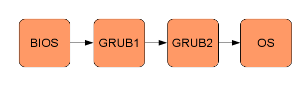
Booting an operating system consists of transferring control along a chain of small programs, each one more “powerful” than the previous one, where the operating system is the last “program”. See the following figure for an example of the boot process:

BIOS
When the PC is turned on, the computer will start a small program that adheres to the Basic Input Output System (BIOS) [16] standard. This program is usually stored on a read only memory chip on the motherboard of the PC. BIOS is a collection of software routines that are initially loaded from a chip into memory and initialised when the computer is switched on. BIOS provides auto-detection and basic control of your computer’s essential devices, such as the screen, keyboard, and hard disks.
Note: Modern operating systems do not use the BIOS’ functions, they use drivers that interact directly with the hardware, bypassing the BIOS. Today, BIOS mainly runs some early diagnostics (power-on-self-test) and then transfers control to the bootloader.
Boot Sector
BIOS cannot simply load a file that represents your operating system from a disk, since BIOS has no notion of a file- system. BIOS must read specific sectors of data (usually 512 bytes in size) from specific physical locations of the disk devices, such as Cylinder 2, Head 3, Sector 5.
So, the easiest place for BIOS to find our OS is in the first sector of one of the disks (i.e. Cylinder 0, Head 0, Sector 0), known as the boot sector. To make sure that the "disk is bootable", the BIOS checks that bytes 511 and 512 of the alleged boot sector are bytes 0xAA55. If so, the BIOS loads the first sector to the address 7C00h, set the program counter to that address and let the CPU executing code from there. This is the simplest boot sector ever:
e9 fd ff 00 00 00 00 00 00 00 00 00 00 00 00 00
00 00 00 00 00 00 00 00 00 00 00 00 00 00 00 00
[ 29 more lines with sixteen zero-bytes each ]
00 00 00 00 00 00 00 00 00 00 00 00 00 00 55 aa
Note that, in the above boot sector, the three important features are:
- The initial three bytes, in hexadecimal as 0xe9, 0xfd and 0xff, are actually machine code instructions, as defined by the CPU manufacturer, to perform an endless jump.
- The last two bytes, 0x55 and 0xaa, make up the magic number, which tells BIOS that this is indeed a boot block and not just data that happens to be on a drive’s boot sector. (in little-endian format)
- The file is padded with zeros (’*’ indicates zeros omitted for brevity), basically to position the magic BIOS number at the end of the 512 byte disk sector.
The first sector is called Master Boot Record, or MBR. The program in the first sector is called MBR Bootloader.
So, BIOS loops through each storage device (e.g. floppy drive, hard disk, CD drive, etc.), reads the boot sector into memory, and instructs the CPU to begin executing the first boot sector it finds that ends with the magic number. This is where we seize control of the computer.
The Bootloader
The BIOS program will transfer control of the PC to a program called a bootloader. A bootloader loads an OS, or an application that runs and communicate directly with hardware. To run an OS, the first thing to write is a bootloader. Here is a simple bootloader.
;
; A simple boot sector program that loops forever. ;
9

; Define a label, "loop", that will allow ; us to jump back to it, forever.
; Use a simple CPU instruction that jumps
; to a new memory address to continue execution. ; In our case, jump to the address of the current ; instruction.


loop:
    jmp loop


; When compiled, our program must fit into 512 bytes,
; with the last two bytes being the magic number,
; so here, tell our assembly compiler to pad out our
; program with enough zero bytes (db 0) to bring us to the ; 510th byte.


times 510-($-$$) db 0


; Last two bytes (one word) form the magic number, ; so BIOS knows we are a boot sector.

dw 0xaa55
We compile the code with nasm and write it to a bin file:
nasm -f bin boot_sect_simple.asm -o boot_sect_simple.bin
Let's try it out:
qemu boot_sect_simple.bin
On some systems, you may have to run qemu-system-x86_64 boot_sect_simple.bin If this gives an SDL error, try passing the --nographic and/or --curses flag(s).You will see a window open which says "Booting from Hard Disk..." and nothing else. There you go, a simple boot loader is ready!
To summarise the control flow of the boot process:
- BIOS transfers control to MBR bootloader by jumping to 0000:7c00h, where bootloader is assumed to exist already.
- Setup machine environment for booting by properly initialize segment registers to enable flat memory model.
- Load the kernel:
(a) Read kernel from disk.
(b) Save it somewhere in the main memory.
(c) Jump to the starting code address of the kernel and execute.
4. If error occurs, print a message to notify users something went wrong and halt.
"Hello World!"
To print Hello World! on the screen, we need to tell the BIOS to print these characters for us. But how does BIOS know how to do that? And where does BIOS store these characters at? It does it with a fundamental mechanism of the computer called interrupts and registers.
Interrupts
Interrupts are a mechanism that allow the CPU temporarily to halt what it is doing and run some other, higher-priority instructions before returning to the original task. An interrupt could be raised either by a software instruction (e.g. int 0x10) or by some hardware device that requires high-priority action (e.g. to read some incoming data from a network device).
Each interrupt is represented by a unique number that is an index to the interrupt vector, a table initially set up by BIOS at the start of memory (i.e. at physical address 0x0) that contains address pointers to interrupt service routines (ISRs). An ISR is simply a sequence of machine instructions, much like our boot sector code, that deals with a specific interrupt (e.g. perhaps to read new data from a disk drive or from a network card).
So, in a nutshell, BIOS adds some of its own ISRs to the interrupt vector that specialise in certain aspects of the computer, for example: interrupt 0x10 causes the screen-related ISR to be invoked; and interrupt 0x13, the disk-related I/O ISR.
However, it would be wasteful to allocate an interrupt per BIOS routine, so BIOS multiplexes the ISRs by what we could imagine as a big switch statement, based usually on the value set in one of the CPUs general purpose registers, ax, prior to raising the interrupt.
CPU Registers
Just as we use variables in a higher level languages, it is useful if we can store data tem- porarily during a particular routine. All x86 CPUs have four general purpose registers, ax, bx, cx, and dx, for exactly that purpose. Also, these registers, which can each hold a word (two bytes, 16 bits) of data, can be read and written by the CPU with negligible delay as compared with accessing main memory.
Let's make the previously silent boot sector print some text using the above concepts
To print something on the screen, we will raise an interrupt inside the infinite-loop boot sector. And to store each character of "Hello World!" word, we will write each character into the register al (lower part of ax), the bytes 0x0e into ah(the higher part of ax) and raise interrupt 0x10 which is a general interrupt for video services.
0x0e on ah tells the video interrupt that the actual function we want to run is to 'write the contents of al in tty mode'.
We will set tty mode only once though in the real world we cannot be sure that the contents of ah are constant. Some other process may run on the CPU while we are sleeping, not clean up properly and leave garbage data on ah.
For this example we don't need to take care of that since we are the only thing running on the CPU.
Our new boot sector looks like this:
mov ah, 0x0e ; tty mode
mov al, 'H'
int 0x10
mov al, 'e'
int 0x10
mov al, 'l'
int 0x10
int 0x10 ;
mov al, 'o'
int 0x10

mov al, ' '
int 0x10

mov al, 'W'
int 0x10
mov al, 'o'
int 0x10
mov al, 'r'
int 0x10
mov al, 'l'
int 0x10
mov al, 'd'
int 0x10


jmp $ ; jump to current address = infinite loop

; padding and magic number
times 510 - ($-$$) db 0
dw 0xaa55
Let's compile the code with nasm and write it to a bin file:
nasm -fbin boot_sect_hello.asm -o boot_sect_hello.bin
You can examine the binary data with od -t x1 -A n file.bin
qemu boot_sect_hello.bin
Your boot sector will say 'Hello' and hang on an infinite loop.
There we go, we just wrote a boot sector in assembly language. All operating systems start this way and then pull themselves up into higher level abstractions (e.g. higher level languages, such as C/C++/Go/Rust).
In the next tutorial, we will see how a stack is implemented and how we can load programs into the bootloader from memory/disk.
Reference:
https://www.cs.bham.ac.uk/~exr/lectures/opsys/10_11/lectures/os-dev.pdf